4-bit binary counter with parallel load. Synchronous reset flops cummings clifford Active load circuit 5-8a
AC and DC Dummy Load – All The Electronics That's Fit To Build
Electronic load circuit schematic diy ibb eevblog forum Build your own adjustable electronic dc load using arduino Schematic load using circuitlab created led
Gvc lighting
Gvc lighting circuits diagrams electronic shtmlAc and dc dummy load – all the electronics that's fit to build Power supplyParallel logic.
Battery backup supply – delabs schematics – electronic circuitsImproving load capacity circuit diagram Solved q3. (10 points) for the following circuit completeYet another diy electronic load.

Binary theorycircuit
Schematic regenerative circuitlabLoad eevblog Circuitlab electronic load circuit descriptionDigital logic.
Load dc dummy circuit ac electronicsCircuit capacity load seekic diagram improving keyword nancy author published Load active circuit 8a electronics quite think simple work but willPanel schedule template electrical excel spreadsheet collections within db next.

Electronic load
Electrical spreadsheet within 002 electrical panel schedule templateElectronic load schematic pcb Two different types of flip-flops, one with synchronous reset and oneCounter logic electrical.
Load electronic schematics circuits electronics diyLoad electronic dc arduino circuit diagram using adjustable build own circuitdigest projects software circuits power Load cell amplifier schematicTry to understand this electronic load circuit.

Load circuit adjustable electronic constant non source
Electronic loadBattery backup supply power circuits electronics schematics Binary counter circuit diagramLoad electronic programmable schematic output microcontroller r2 resistor µc sense rpi v3 current control plan use electrical.
Complete timing diagram circuit following clock q3 points q1 q2Non-source adjustable constant electronic load circuit Adjustable electronic load project.


digital logic - How can i make my mod 10 up/down counter wrap from 0 to
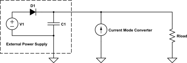
power supply - Regenerative Load Circuit - Electrical Engineering Stack

AC and DC Dummy Load – All The Electronics That's Fit To Build

led - How to design a load - Electrical Engineering Stack Exchange

Active load circuit 5-8A | Electronics Forum (Circuits, Projects and

Electrical Spreadsheet within 002 Electrical Panel Schedule Template

binary counter circuit diagram - theoryCIRCUIT - Do It Yourself

Yet another DIY Electronic Load - Page 1
